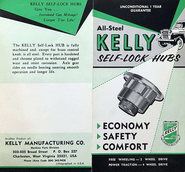
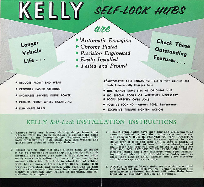
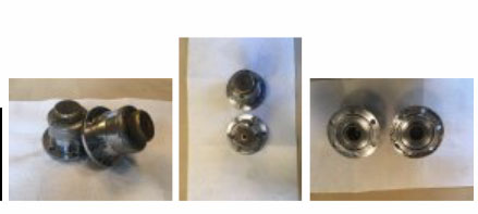
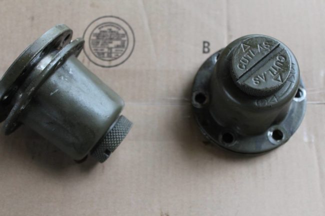
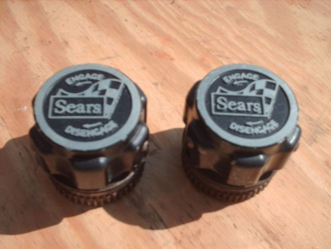
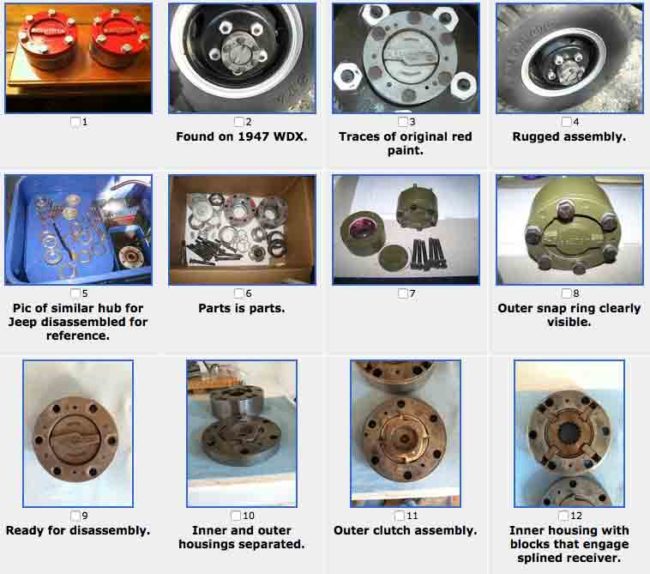
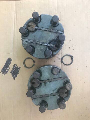
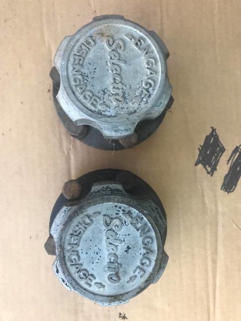
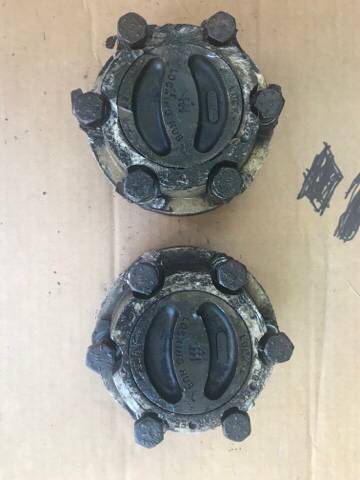
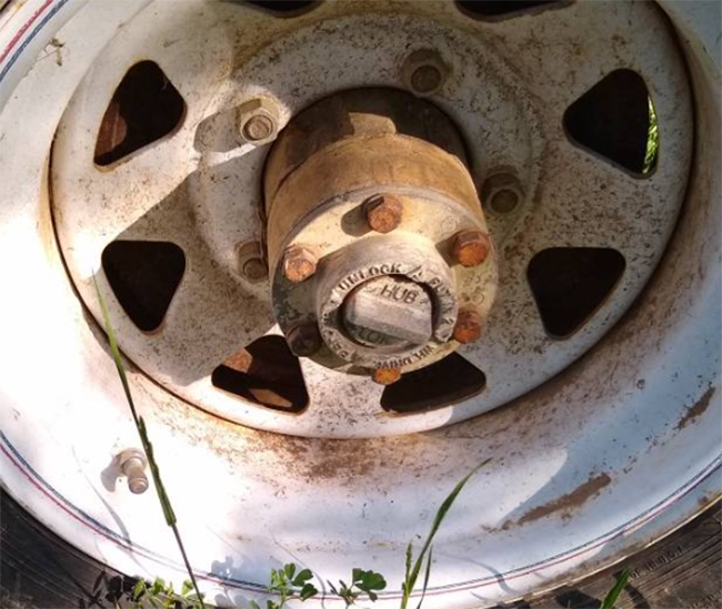
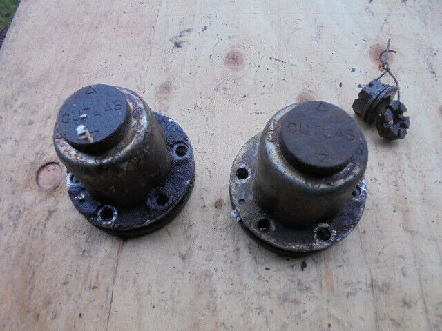
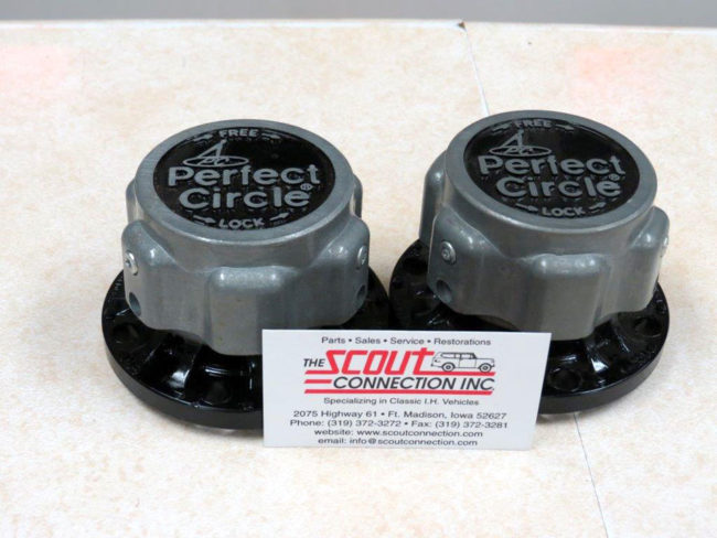
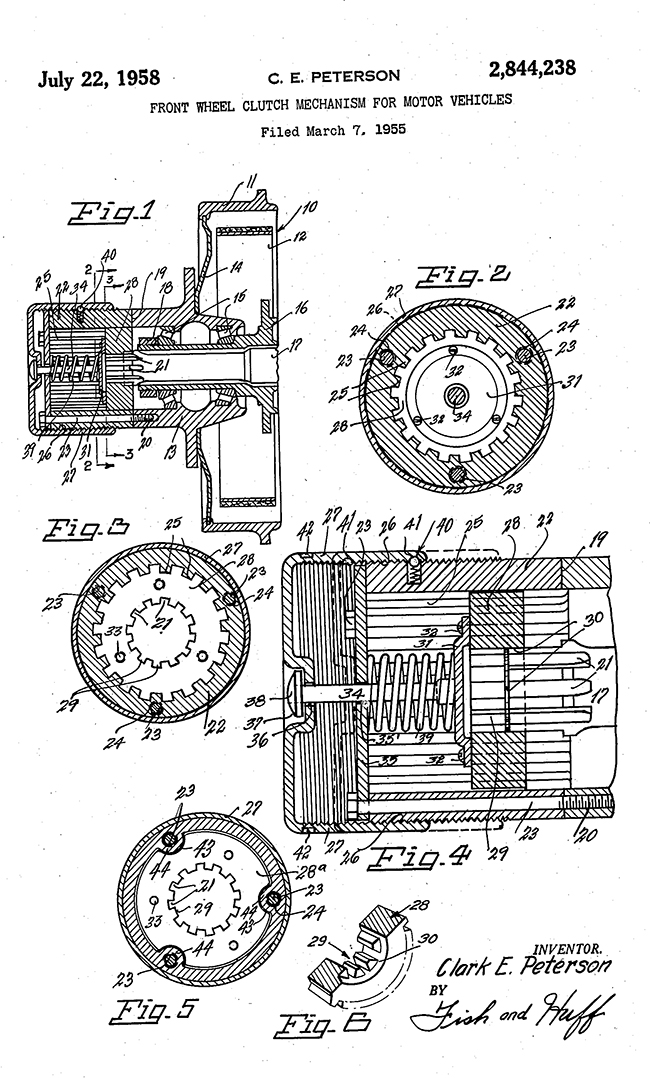
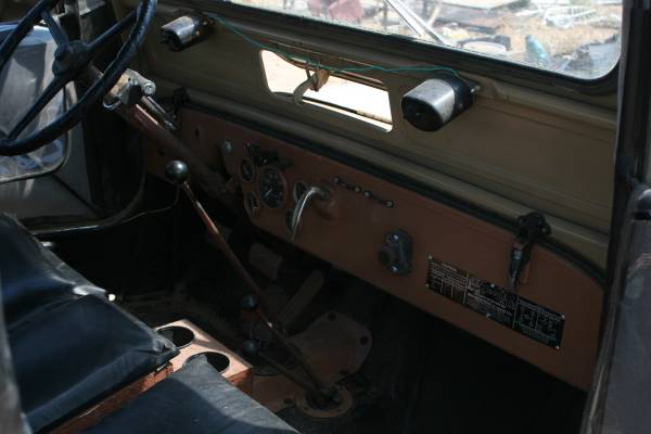
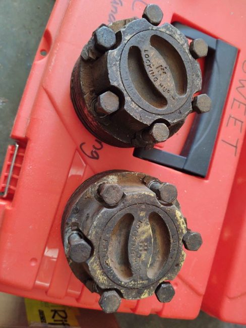
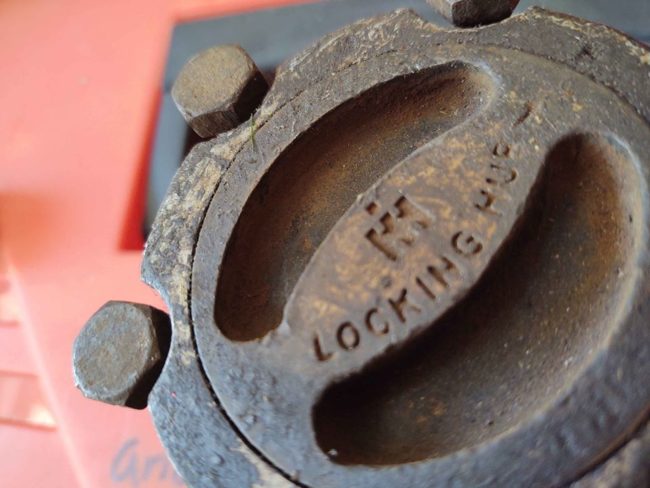
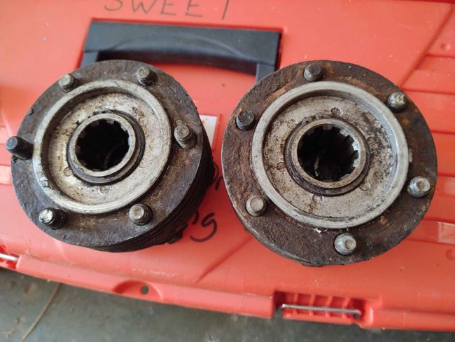
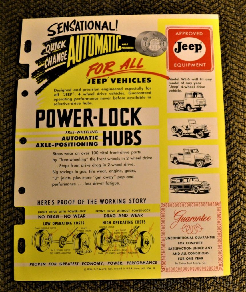
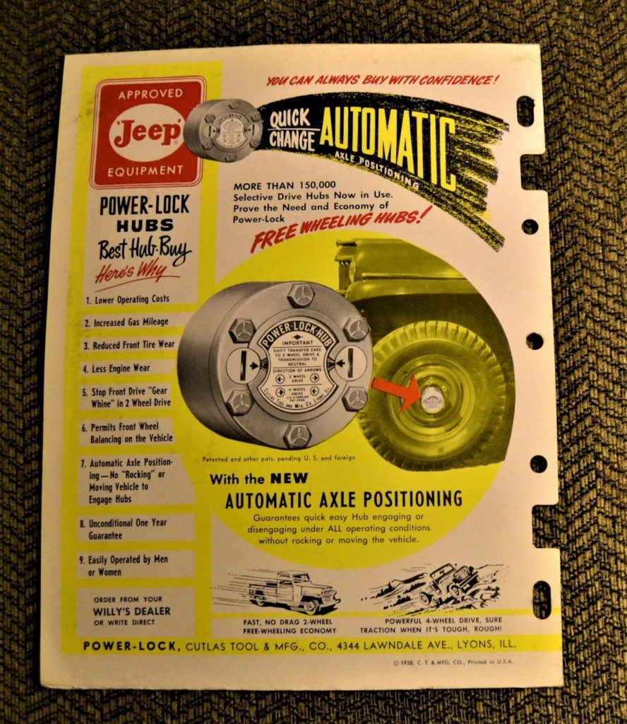
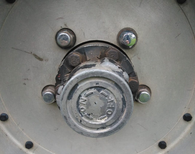
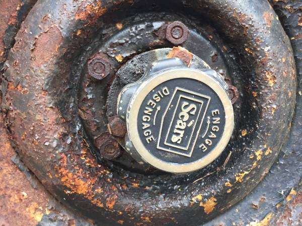
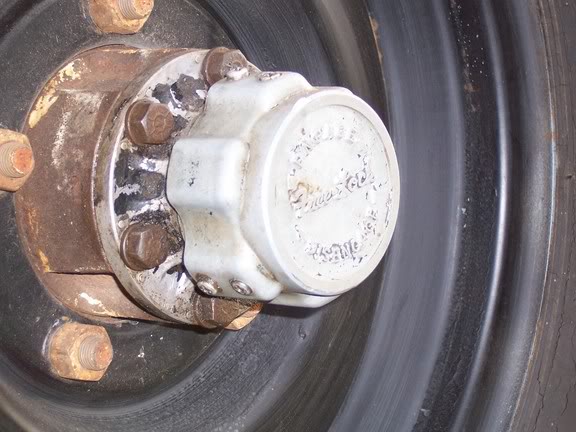
John recently rebuilt a set of Cutlas Selective Hubs, the type with the knob that rotates to engage and disengage the hub. There appear to be at least two styles of these hubs, one with a flat top and one with a groove, so that a tool (or improvised tool) can be used to help engage, disengage the hub.
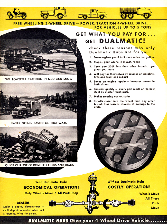
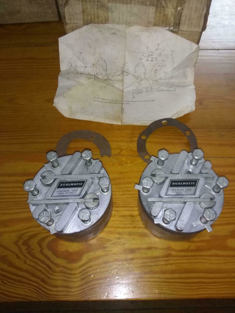
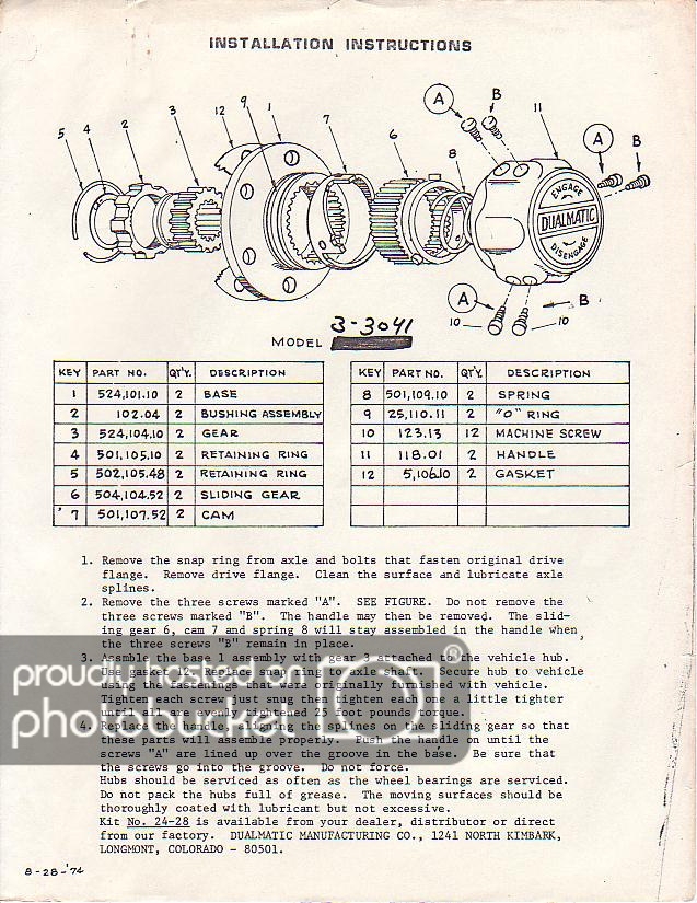
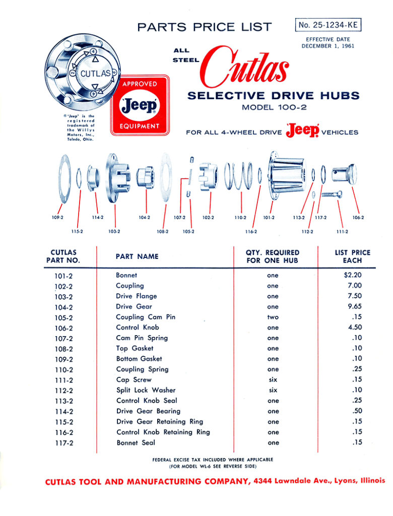
This exploded overview from 1961 shows how the parts assemble (see the full brochure below this post):
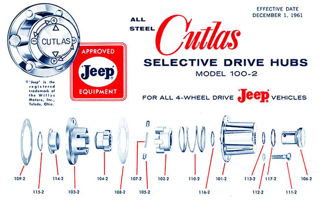
As you can kind of see from this diagram, there are two sections: 1) is the hub cap that holds the knob and the spring in place (from part 107-2 in the middle and everything to the right of it) and 2) the hub base (part 108-2 and everything to the left of it).
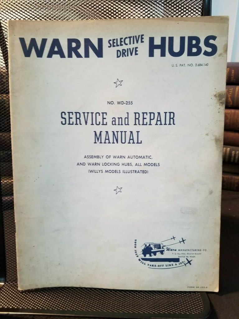
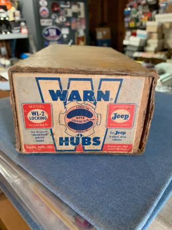
John wrote, “Overall I’d say these are my favorite hubs I’ve worked on so far. I have a pair of Warn hubs (with the tiny needle bearings) and a pair of Selectro hubs (big chrome knob type). The Warns seemed like a real pain to rebuild since the needle bearing were in rough shape. And the Selectro hubs, while very easy to operate, were probably the weakest design I’ve seen.”
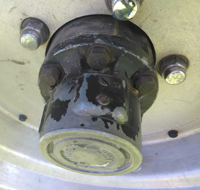
Here’s a look at John’s finished product, as it’s the best example a complete hub next to a hub with the top separated from the base:
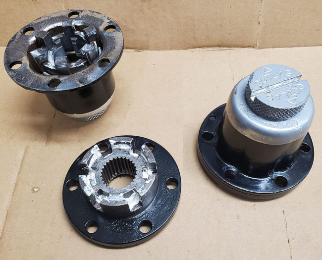
I went with a 2 tone paint job just for fun. If it doesn’t last for any reason I’ll end up with the whole thing gloss black and a chrome knob. The body was so badly pitted there was no saving the original finish
HUB CAP:
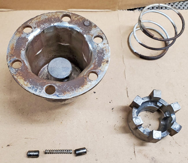
We’ll start with the hub’s cap first. John provided the following note: “To remove the coupling piece (part 102-2 Coupling) from the chrome cap (with the cutlas knob) you have to line it up right with the correct groove, then push down firmly against the spring inside (part 110-2 coupling spring). While pushing down spin the coupling, and then the coupling spring will pop the coupling right out and its free.”
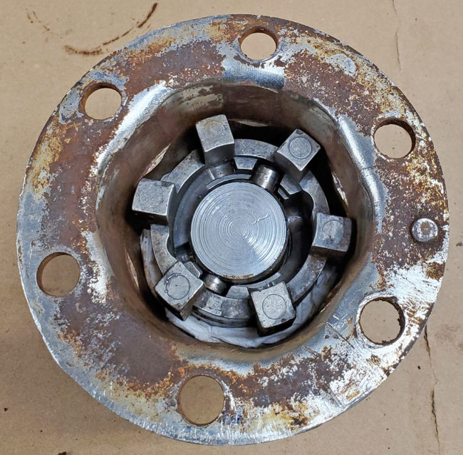
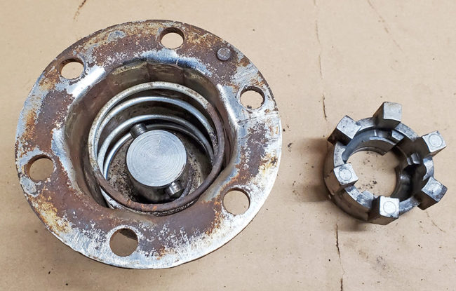
With the inner portion of the cap apart, you can see the coupling ring, the coupling, the coupling cam spring (part 107-2) and the coupling cam pins (parts 105-2).
Continue reading →





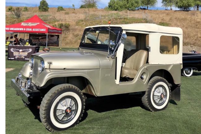
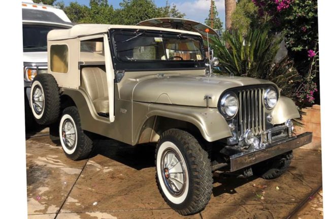
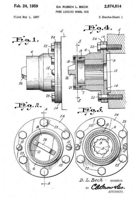
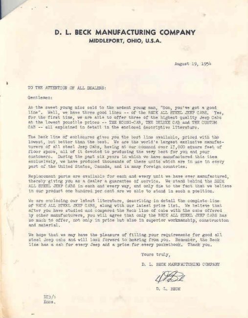
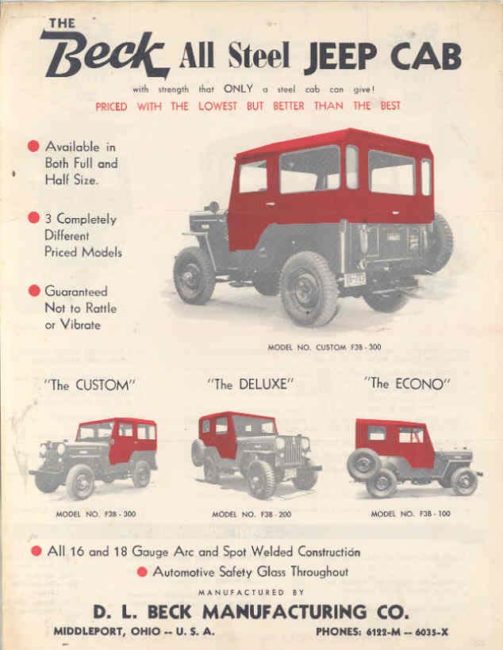 Beck sold his hardtop company to Hubert A. Kelly, in the 1950s but Beck and Kelly remained in contact. The date of the sale, thought once to be 1951, is less clear after this document hit eBay in 2014. It indicates Beck was still selling hardtops in 1954.