Biscuit Research Archives

My Rebuild

To Top

My Build: Transfercase cover

• CATEGORIES: Biscuit This site contains affiliate links for which I may be compensated.

I’ve been attacking a variety of little projects to get the jeep complete.  One of those is the transfercase cover.  Mike and I had done a little trade out of which I received a stock CJ-2A rubber boot, but after testing it out, I decided it wouldn’t work.  So, I ordered a beefier and larger Dana 300 boot that did the trick.

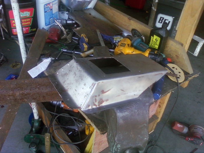
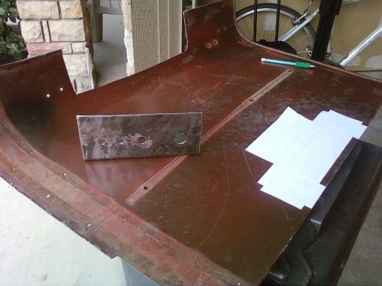
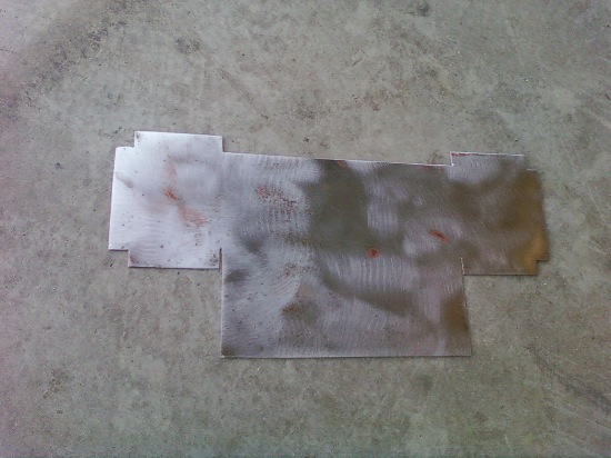
In order to mount it, I had to build a metal cover to secure the rubber boot.  I turned to my old dissected hood for some metal.  I then cut a hole the side of the boot, drilled some holes along the side, and mounted it to my fiberglass.

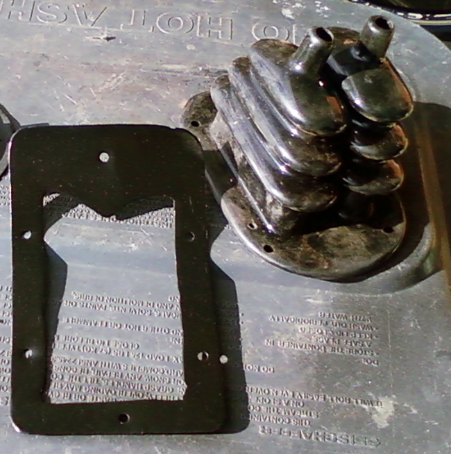
Below is the Dana 300 boot and the metal piece I made:

transfercase_cover1

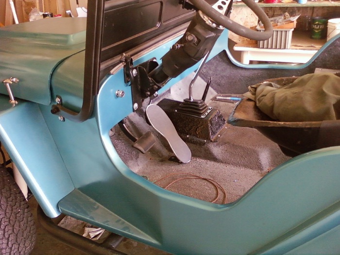
Below is the hold I needed to fill:

transfercase_cover2

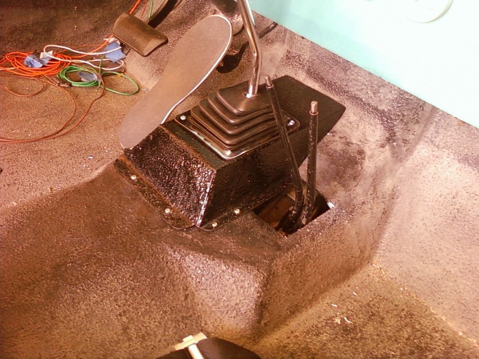
And here it is filled.  Nothing fancy:

transfercase_cover3

 
To Top

My Build: Mufflers

• CATEGORIES: Biscuit This site contains affiliate links for which I may be compensated.

UPDATE:  I reported last week that I got my mufflers attached.  Here’s some pics of that. On my last jeep, I never liked the way I connected my mufflers, so I decided this time I would create a more secure setup.

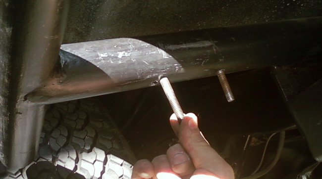
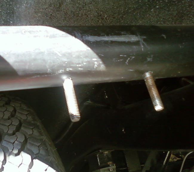
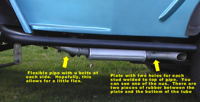
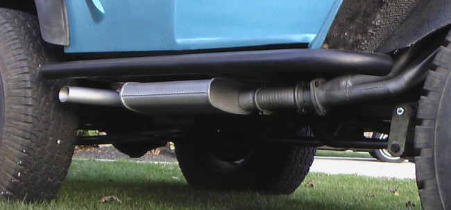
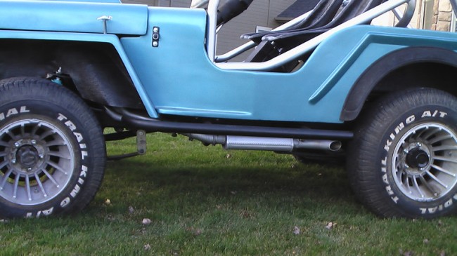
To start, I select some ‘Cherry Bomb’ mufflers that were the smallest, least expensive ones I could find at my local Schucks store.  Between the headers and muffler I added a short piece of flexible pipe, in part to provide a little flexibility and to turn the corner underneath the front cage mount.  Behind the muffler, I connected a tube with a 50 degree bend and an angle cut at the very end.  To the tailpipe I also welded a flat piece of steel with two holes so that I could connect the muffler section to the bottom of the tube show in the pics below.  You can see that I drilled a holes and inserted studs, which I welded in place,  so I could easily connect the mufflers.

muffler4

muffler5

muffler6

muffler2

muffler1

 
To Top

My Build: Where to put the CB?

• CATEGORIES: Biscuit This site contains affiliate links for which I may be compensated.

The last time I did any serious jeeping was long enough ago that I’d never heard of a cell phone.  Instead, we communicated wirelessly through a really hot technology called a Citizens Band (CB) Radio.  It was long enough ago, that CBs were still cool.  It was amazing.  We could all communicate, sort of, in between static, wirelessly.  It was so cool!

So, of course, Biscuit’s an old school jeep, so it has to have a CB.  Fortunately, among the parts jeeps I purchased a couple years ago, I managed to recover 2 CBs, one of which still works.  I figured that there still aren’t any cell towers on the Naches Trail (please don’t tell me if there is … I’m turning off my cell phone … turning on my CB, so I can listen to it crackle), so I’ll still get to use a CB, even if it is less frequently than before.

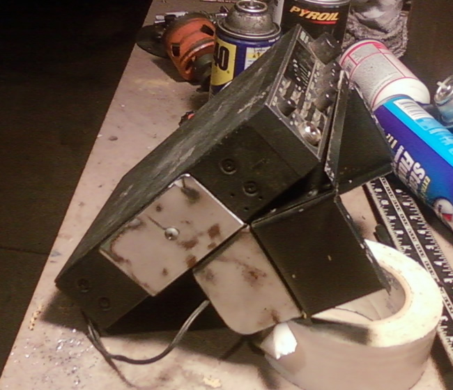
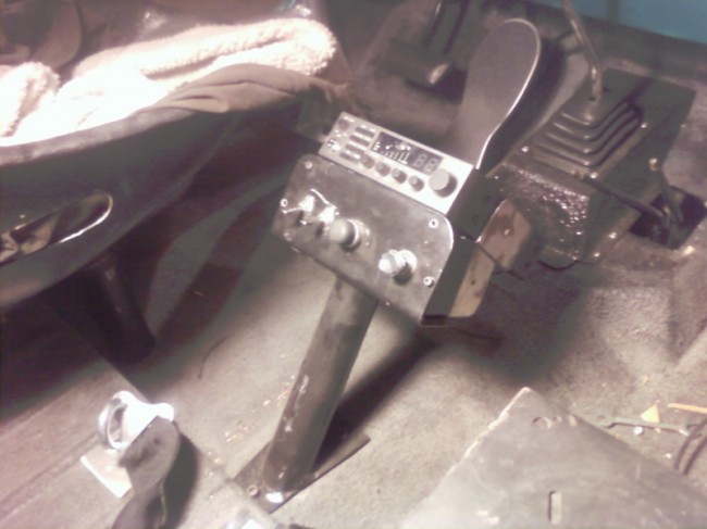
Now that I’ve decided to install a CB, where do I put it?  I considered a couple options (hang off the front roll bar loop/ off the dash board / off the windshield), but decided I would piggy back it onto my center console (documented here).  I used some flat steel from a different part of the same chunk of hood that I used to make the console.

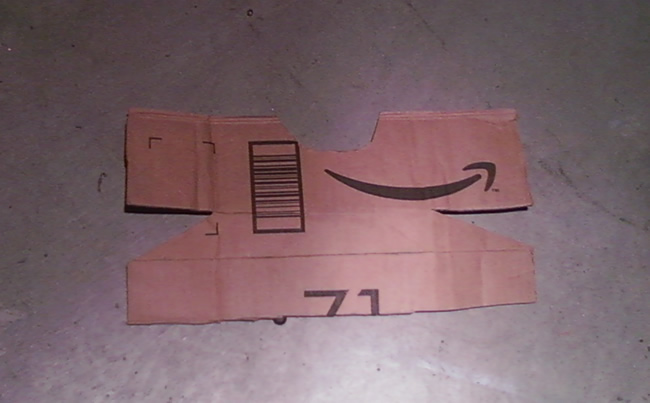
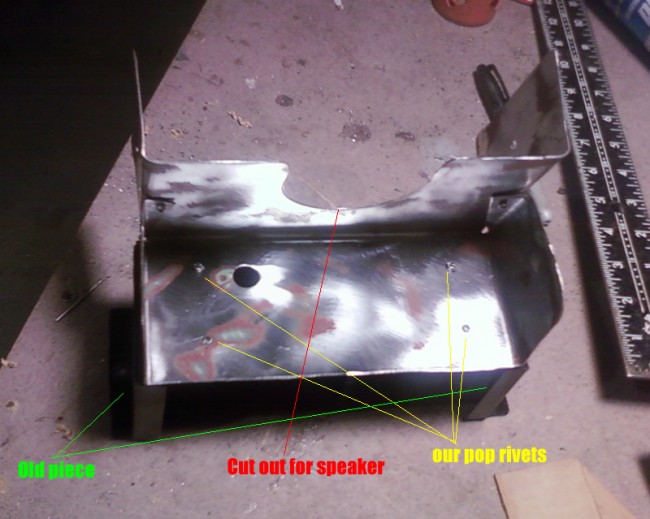
Here’s the basic pattern I cutout.

cb_the_pattern

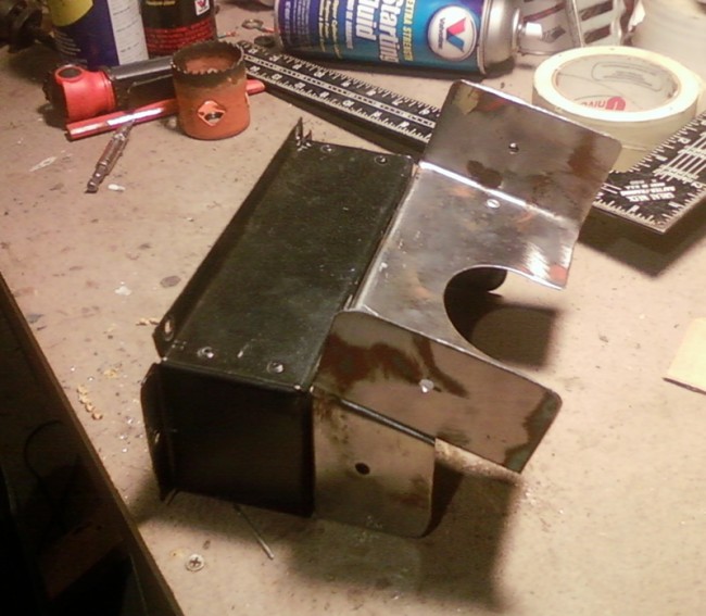
After cutting the piece out of the hood, I sanded it and bent it.  Then, I drilled some holes between the old piece and the new piece and used poprivets to connect them.

cb_inprogress1

cb_inprogress2

cb_inprogress3

Below the console is installed, though not painted yet, showing how the CB will sit.  The power wire and antenna wire will feed from the console.  You can see how scratched up the console is already.  I’m saving the repainting for the next, inevitable, rebuild.

cb_final

 
To Top

My Build: Cage Painted and Installed

• CATEGORIES: Biscuit This site contains affiliate links for which I may be compensated.

TABLE OF CONTENTS: There’s 4 sections to this post:

  1. 1. My Completed Cage in my jeep
  2. 2. What I thought about when building my cage
  3. 3. Links to dicussions about my cage
  4. 4. Other roll cage images


1.  MY CAGE:
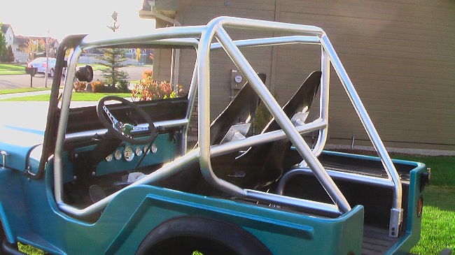
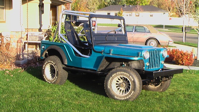
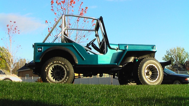
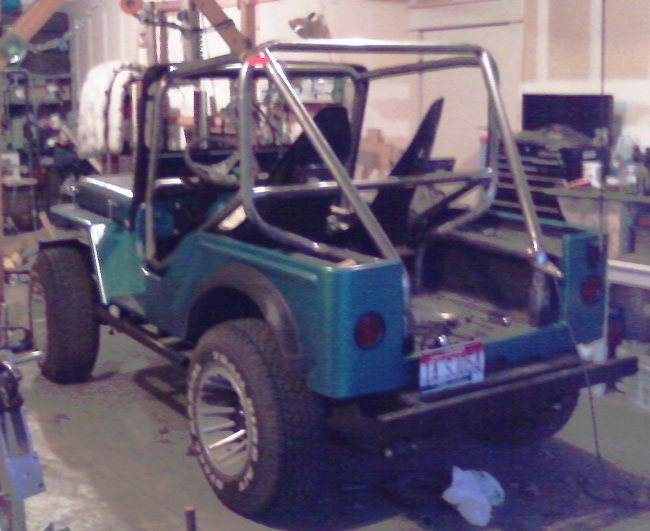
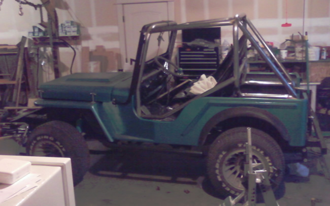
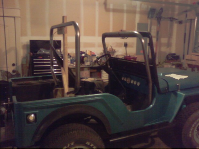
Here’s the cage in the jeep.  Yeah, I’m happy about this.  It’s a little chromier color than I wanted, but I suspect I’ll be covering it with wrap soon.  I already hit my head once, lol …

biscuit_rollcage6

biscuit_rollcage10

biscuit_rollcage11

biscuit_rollcage8

And here’s a video:


2. MY THOUGHTS ON BUILDING THE CAGE

And an overview of my experience:

This post reflects my experience researching and building my roll cage.  My goal with this post is to eliminate the need for others to spend the hours and hours I spent researching weighing options and deciding upon a cage.  Note that while I have had a couple cages and my dad built two cages (back in the 70s), this was the first cage I designed, bent and built myself.

CLICK ON THE LINK BELOW TO READ MUCH MORE ….

Continue reading

 
To Top

My Build: Cage is ready for Sanding and Paint

• CATEGORIES: Biscuit This site contains affiliate links for which I may be compensated.

The day has gotten away from me, so this will be the only post tonight….

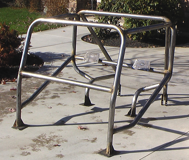
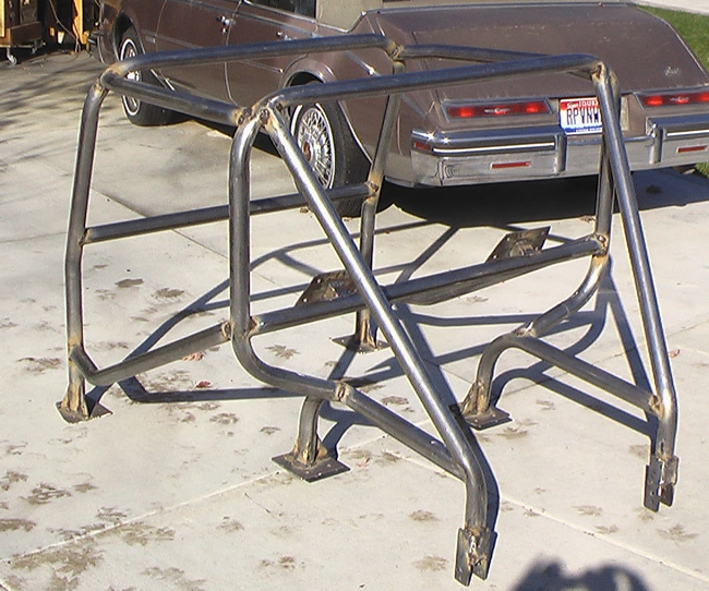
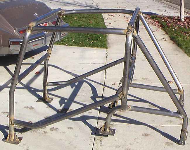
Today I completed the welding of the cage.  The below pictures show the cage prior to some grinding (and a little more welding and a little more grinding).

As I mentioned yesterday, I hadn’t decided on a paint color.  So, I visited the maker of the paints (Van Sickle Paints – Tractor Paints) I have used on the frame (one thing I really like about the paints is that they have a nice thick brush on color as well as a matching spray color).  It turns out, they have an ‘aluminum color‘.  So, I’m gonna give the aluminum color a try (I don’t really have high hopes to be honest).  The worst case scenario is I hate it; so then I’ll just paint it black.

Here’s a few pics from today:

rollcage_complete

rollcage_complete2

rollcage_complete8

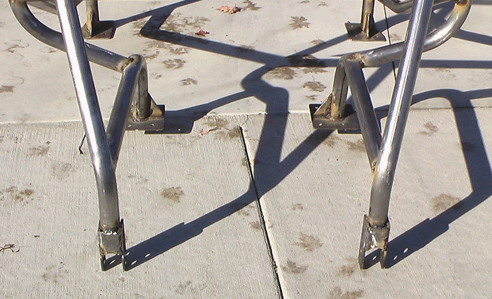
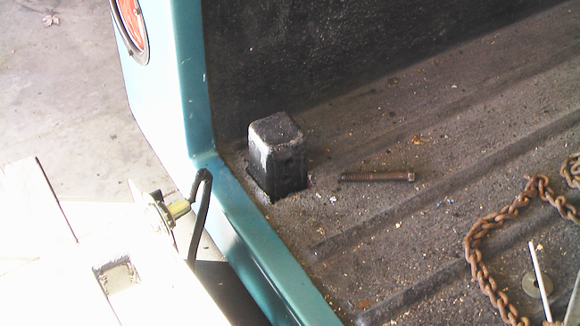
Below is a close up of the back connectors. And in the pic below that, you can see the posts to which the back of the cage connects.  There are two bolts per side.  The bottom of the rollbars actually rest atop the post.  The reason I built this like this was because of a problem I ran into with my last jeep:  It was difficult to run the gas tank hose by the rear passenger-side cage connector.  To bypass that problem this time, I’m trying this post approach.

rollcage_complete4

rollcage_back_connect

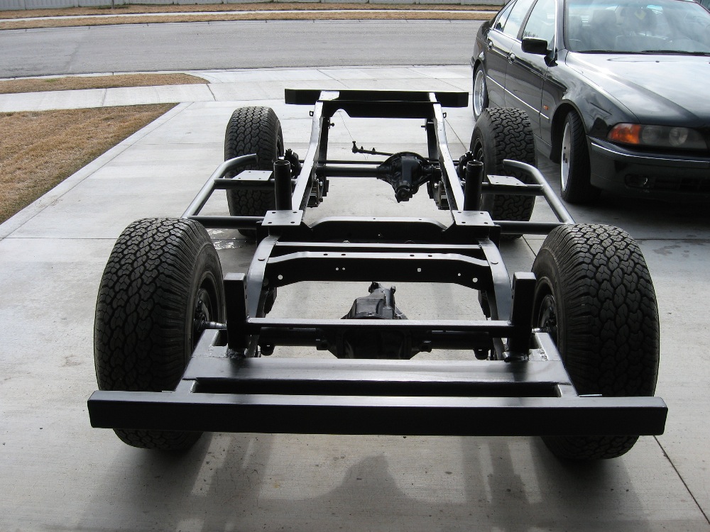
Here’s a picture of the raw frame with the posts in the foreground, along with the middle loop platforms and front loop platforms.  The round posts support the seats (the seat platform actually screws onto the top of those round posts).  The round posts were invaluable in acting as a precise guide when placing the body onto the frame, keeping everything well aligned.

You can see more of the frame here http://www.ewillys.com/?p=417

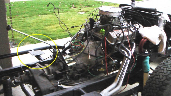
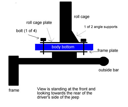
Here’s a look at the front roll cage platforms and a drawing of how the connection occurs.

rollcage_connection_to_frame

rollcage_drawing_connection

 
To Top

My Build: More Roll Cage Progress

• CATEGORIES: Biscuit This site contains affiliate links for which I may be compensated.

I managed to get as far as I hoped to get today.  I got all the pieces fitted with welds mostly completed.  I expect to have it ready for paint by tomorrow.  I was going to paint the cage black, because I was planning on wrapping it with padding, but I’m liking the silver metal color, so I am considering some kind of metalic color.

rollcage_10_24_09

rollcage_10_24_09_3

rollcage_10_24_09_2

 
To Top

My Build: More Progress on the Cage

• CATEGORIES: Biscuit This site contains affiliate links for which I may be compensated.

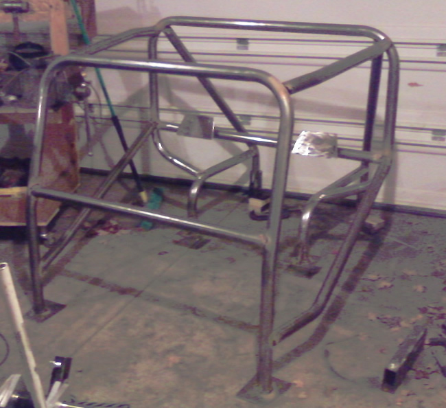
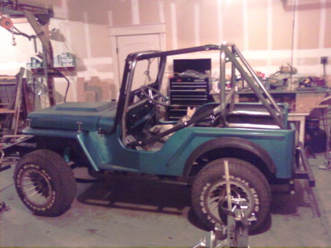
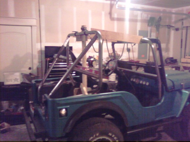
The cage is starting to take shape.  It’s only tacked together at the moment and the ‘spreader bars’ between the front and back loop are still PVC.  The lower of the spreader bars isn’t at the correct angle either, but the real bar should be in by tomorrow.

rollcage_jeep_10_21_09

 
To Top

My Build: Roll Cage Day 2

• CATEGORIES: Biscuit This site contains affiliate links for which I may be compensated.

Well, I didn’t get as much progress done today as I planned (like I ever do?), mostly because I slept in — way in!  I spent much of the afternoon, moving, measuring, leveling, thinking and then removing, remeasuring, releveling … I think you get the picture.  It took me a while to realize that my windshield is a little crooked and that was throwing me off a little.  Once I figured that out,  I started making progress.

The first thing I did today was to brace the loops into place so I could start adding supports.  I did some cross tubes first.  This helped square the loops, which were off about half an inch each.  Once that was done, I started on the rear supports.  I’ve got a little grinding left on the driver’s side left rear piece then it will be ready to be tacked into place.

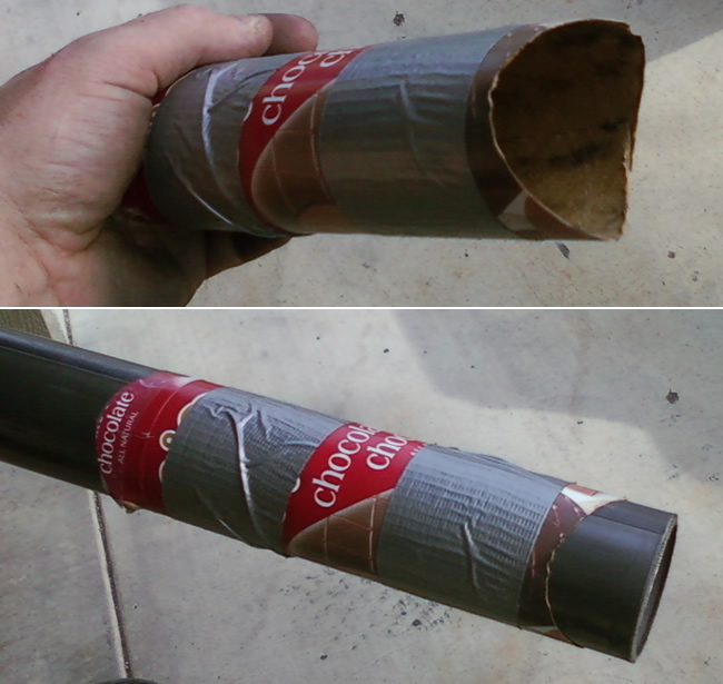
For my tube intersections, I’ve been using this tube coping calculator.  I found it off just slightly, but close enough to be of real value.  I taped the paper to a thin piece of cardboard (my Haagen Dazs Ice Cream boxes work great — A great excuse to get Dark Chocolate/Dark Chocolate Ice Cream Bars).

rollcage_joint_template

Tomorrow evening I’ll complete the back area and start to work on the top side pieces.

Here’s the only pic I have from tonight.

rollcage_sunday_night

 
To Top

My Build: Bending the Rollcage

• CATEGORIES: Biscuit, Idea Factory, Roll Cage This site contains affiliate links for which I may be compensated.

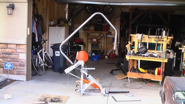
I spent much of the day doing the initial bending of my cage. I managed to complete the front loop and back loop. I was very pleased with the results and the bender. Thanks to Mitch for the front and back loop measurements. Those proved invaluable!

I will delay a discussion of my tube choice (size and type).  I spent A LOT of time researching various forums on the pros and cons of various sizes.  Then, there’s the whole DOM vs. HREW vs. CREW vs. Sched 40 vs. Chromoly … and more.  I’ve also been filing away various roll cage designs so that readers and builders can see all the different ideas.  In the end, my cage reflects the need to tie into my frame due to the fiberglass body, I also wanted it to look like my previous cage in my first jeep, and it includes a workaround for the mid loop attachment as I put the mid loop attachment closer to the seat then I wanted (oops). I also need to talk a little about the bender I built and the plans I used, but will save that for later too.

bender_first_bend

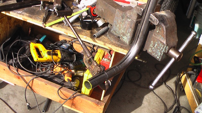
tube_cutterThe first thing I needed to do was calculate exactly how the bend of the tube changed the measurements and determine the inner and outer radius measurements so I could measure the loops correctly. I started by marking off a tube in 1 inch increments up to about 15″. Then I put the tube in the bender and bent the tube. I learned that my 2″ die created an outer radius of 7.5″ and the length of a 90 degree bend from start to finish was 10″.  You can see the inch markers and the tube cutter I was using in the pic to the right.

Another thing I learned was that I had to bend the tube about 3 degrees past the amount I wanted, as it would spring back 3 degrees when released from the bender (you can see it bent past 90 in the pic below).

Knowing that information, I measured and bent the front loop. The first two bends of 90 degrees went smoothly. Then, I cut down the bottom pieces so that, after I added the windshield contours, the front loop would measure 45″ from the loop to the floor boards. Next, I bent the loop with the windshield angle. My windshield sits at an angle of 15 degrees and the bend needed to start 20″ from the floor board. These also bent perfectly.

bender_back_loop_2ndbend

bender_front_loop

So far so good.

Next was the back loop. Based on Mitch’s measurements and the look I was after, I decided that 43″ from the loop to the back floor would be a perfect distance. I made the width the exact distance between the body sides, which is slightly narrow than a standard jeep due to the wider lip on the fiberglass body. Again, the 90 degree bends went perfectly. Then, I had to do 45 degree bends back towards the body. Unfortunately, after testing the loop on the jeep, 45 degrees wasn’t the angle I actually needed, so I had to bend both sides twice in order to increase the angles to the point where it would work correctly.

bender_midloop_beforebend

bender_back_loop_4thbend

Here’s a poor quality shot from my camera phone of both loops in their respective places.

bender_2loops

With the two toughest parts of the cage out of the way, the sun set and I moved inside. I also was getting a little tired, because when I attempted to bend the back supports, I managed to bend BOTH wrong — one was bent the wrong angle and one was bent in the wrong location. Fortunately, I can salvage the tube and use them in other places. At that point, I thought it best to head inside and cook dinner.

More pics tomorrow night.

 
To Top

My Tube Bender

• CATEGORIES: Biscuit This site contains affiliate links for which I may be compensated.

UPDATE:  I’ve added some final information to this post …

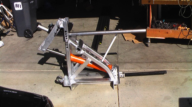
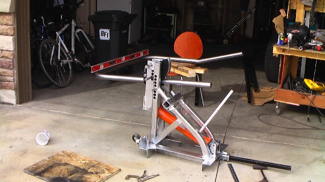
After a great deal of research, I felt the best option for a bender for my purposes was to build my own.  I quickly settled on Frank Takac’s plans from gotTrikes.com. Frank was great to deal with,  responsive to my email and the plans were  professional with plenty of tips, pics and information.  Frank told me that a 15 year old successfully built one of his benders.  You can see a variety of benders built by purchasers of Frank’s plans at his website.  I can strong recommend these plans if you are considering building your bender.

Frank recently added my project to his website.  You can view it here.

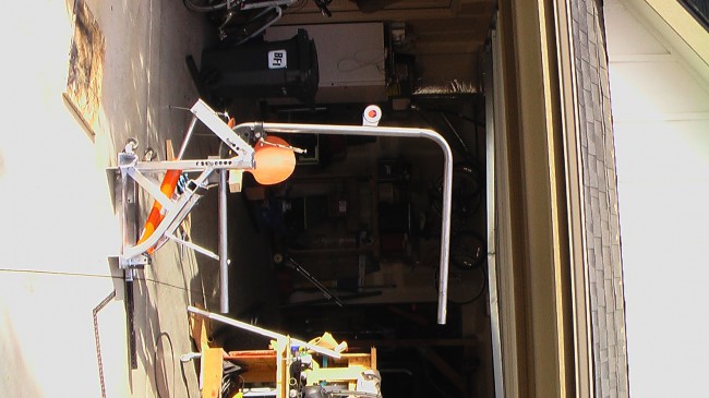
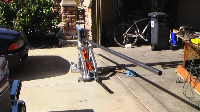
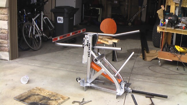
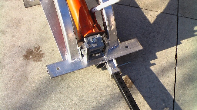
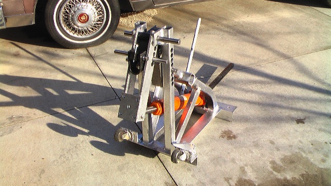
Here’s a few pics of my finished bender:

tube_bender2

tube_bender1

tube_bender6

tube_bender5

PREVIOUSLY:

I’ve been slowly building my tube bender.  I followed most of the instructions I purchased (which were great — I’ll write more about that later), but I just couldn’t stand buying new metal when I had so much 1/4 inch angle iron laying around (thank you sis!).  So, I made several modifications based on the metal I had.

Also, during the process of building, I realized I just didn’t care whether the bender looked good (such as grinding welds, sanding it down, etc).  So, it is what it is.  I did have some leftover chrome paint, if not smooth, it is shiny.  I’m just waiting for a couple shafts to arrive in the mail and then I can start bending!

bender1

bender2

bender3

 
To Top

My Build: Brodie Knob Installed

• CATEGORIES: Biscuit This site contains affiliate links for which I may be compensated.

Sometime next week I hope to be bending my roll cage with my home-made tubing bender.  I’m waiting for the die to get here still.  I’m also waiting for the delivery of my windshield and cowl rubber so that I can get my windshield all ready to go.  In the meantime, I’ve been busy updating the website and doing a few things to the jeep.

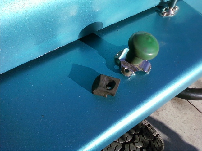
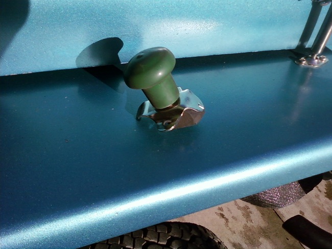
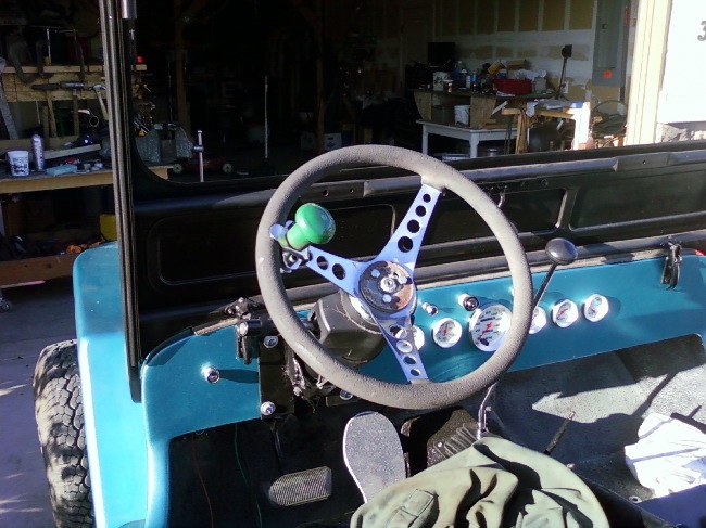
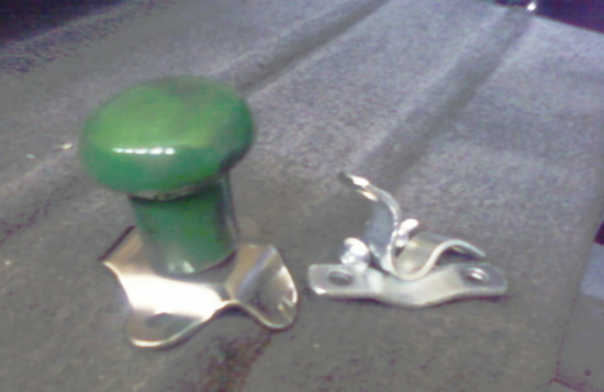
One of those things was the installation of my brodie knob.  I discovered I could cut down a piece of rubber that I think was used by my dad when he installed his CJ-5 body on it’s frame.  It was the perfect thickness, so I cut it down, shaped it and installed it.  It’s nice and tight.  Here’s a few pics.

brodie2

brodie1

brodie3

 
To Top

Buick v6 question … Optimal oil pressure?

• CATEGORIES: Biscuit This site contains affiliate links for which I may be compensated.

UPDATE: I had installed this adjustable pressure regulator from TA performance when I built the engine.  Today I attempted to adjust the regulator to lower my pressure, but it was already adjusted as far out as I could adjust it.  So, took it out and replaced it with the original stock spring and plug.  Sure enough, the pressure dropped to 50psi on idle, though it still climbs to 70psi when revving the engine.

Maybe this is related to all buicks and not just the buick v6?? I’m wondering if my oil pressure is too high, which is causing a couple problems, such as oil dripping out the dipstick hole where the dipstick meets the block.

It seems to me my that on my old 225 odd fire, the pressure was around 40psi and would drop as I accelerated (which was a problem, that finally resolved itself when my engine blew up after about 3 years of good use).

Now, it sticks solidly at 70psi and that’s without a high volume oil pump.  I have a concern that the oil will be spraying rather than dribbling out the mains, which might cause some problems as well? (I read that somewhere)  I can resolved the problem easily by putting  weaker spring in .. I should have one somewhere.

Any thoughts?  I tried to find something on the internet.  The only think I found was that a normal 225 v6 runs about 40psi.

– Dave

 
To Top

Attaching a Brodie Knob

• CATEGORIES: Biscuit, Features, Website This site contains affiliate links for which I may be compensated.

brodie_knobOne of the positives about living in Idaho is that there are lots of tractors and tractor stores nearby.  I stopped by one today and picked up one item I hadn’t yet purchased: a steering knob for my steering wheel for only $6.99 — the best price I’ve seen anywhere (I got it at D&B, a local farm/garden store).  Now, these aren’t legal in every state, but they are sure handy for jeeping and racing.

I brought it home ready to mount it, but realized I couldn’t remember exactly how to mount it, so I jumped on the internet.  The first thing I learned that a steering knob was actually called a Brodie Knob, which is where the term “doing a Brodie” comes from.

From Wikipedia, “Brodie Knobs were widely popularized, especially on the west coast of the U.S., during the 1950s. Their intention was to be used primarily as addition to a Hot Rod. The knob was used to spin the steering wheel, rapidly in one direction or the other, while accelerating, to cause the tire(s) to spin while rapidly whipping the car 180 degrees or half of a “doughnut”. Hence, comes the term “lay a brodie”. In the 1950s and 60’s a person could go into any local “Pep Boys” and choose from a large variety of brodie knobs, with every conceivable theme, from “Candy Apple colored”, “Product Logos”, to “nude women,” and everything in between, some automobile dealerships even used them for advertisements. They were very useful during a period of auto manufacturing, when power steering was truly a luxury…. ”

thehotrodgirl_2064_125192I also discovered that there’s a wide variety of knobs that I didn’t know exist.  For those growing up in the world of hotrods, they probably aren’t surprised, but the knobs I have seen are generally all tractor related. Other names for the Brodie include the Suicide Knob, Granny Knob, and Steering Wheel Spinner

Check out the different kinds of knobs offered through thehotrodgirl.com.

 
To Top

My Build — One of those days …

• CATEGORIES: Biscuit This site contains affiliate links for which I may be compensated.

I went out today to start the jeep.  The battery was completely dead.  This is the first time I have had any problems with the battery.  Something drained the battery significantly.  The only change I have made was plugging in the head lights, so I will have to do some more investigation into this.

But, I don’t give up easy.  I wanted to run the engine, so I jumped the jeep and got it going.

I ran it half way around the block to help charge the battery.

Exactly half way around the block I ran out of gas.  I knew my gas guage sender needed to be adjusted, but I still thought I had a little more gas.

I coasted to a stop … alternatively laughing and cussing.

So, I went and got gas from my garage, got the truck, put in some gas, jumped it once more, ran it home and put it quickly to bed.  Tomorrow I go get a battery charger …. lol.

 
To Top

My Rebuild: Creating the Transmission Cover

• CATEGORIES: Biscuit, Features This site contains affiliate links for which I may be compensated.

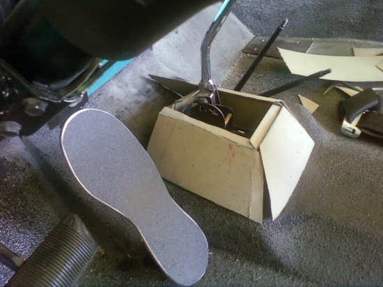
Another of the projects I was putting off was the creation of a transmission cover. It’s really nice to be crossing these small projects off the project list. It’s not a thing of beauty, but it will do for now.

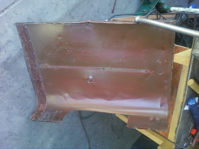
It turns out that the bad hood I had from one of the jeeps I purchased has been a great source of foldable, flat steel. So, I used a chunk of it to fold together a cover.

Before doing any cutting, I used some cardboard pieces to create a mockup. Here’s a look at most of the pieces in place (I actually had more, but removed them, then realized I hadn’t taken a pic, so I threw a few of them back on ..)

tranny_cover_mockup

Here’s a pic of the flat steel from the hood:

tranny_cover_beginning

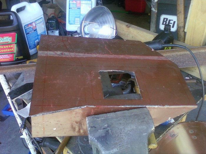
Next, I drew some basic lines that I used as an outline for cutting and bending the piece. Then, I used a cutting wheel to create a rough cutout of what I wanted. Boy I wish I had had a cutting wheel for my first jeep! That little 4.5″ cutting wheel has been invaluable.

Once I did a rough cut, I made an initial bend (note the clean working space .. lol):

tranny_cover_cutting

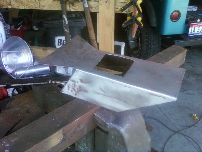
Because of the odd and curved shapes, I cut a little, tested it, cut a little and tested it again. Once I was convinced it would work, I sanded it down and made some additional folds:

tranny_cover_bending

After testing it some more, I made the last fold and riveted it in place.

tranny_cover_almostdone

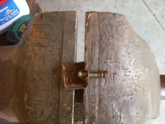
With it finished, I drilled the holes necessary to mount the rubber boot on top and to attach the cover to the body.

All that was left to do was to paint the piece with Herculiner to match the body floor. By this morning the paint was dry, so I installed the cover:

tranny_cover_final

And, from the other side:

tranny_final_cover2

Once I grab a rubber dual boot for the transfer case shifter (if any one has one of these, I’m open to a trade or cash!),  I’ll create a small piece to complete the cover.

 
To Top

My Build: Headlight Rebuild

• CATEGORIES: Biscuit This site contains affiliate links for which I may be compensated.

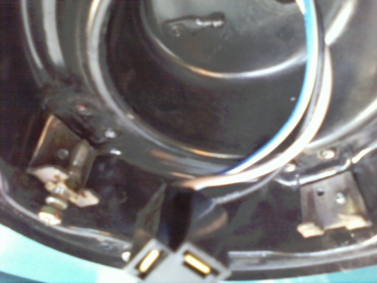
One of the projects I have been putting off is the rebuild of my headlight containers.  The headlight directional adjustment pieces were made of plastic. Two of the four had already broken, so I knew I’d have to fix them eventually.

After pondering the situation, I chose to remove the existing directional adjusters off the CJ-3A headlight containters I had.  I really hate damaging these original pieces, however I also knew that the oldsmobile units I use are even harder to find.

Here’s what the original headlight adjusters looked like:

headlight_old_pieces

Here’s a closeup of the plastic piece (out of focus):

headlight_old_piece1

Here’s the ‘new’ piece that has been cut down so that it will fit (another beautiful pic .. not)

headlight_piece_new

Here are the pieces riveted onto the headlight container.  One more rivet to go.  You can see the old, (blurry) rivets just underneath the new pieces.  Once these were installed, I painted them and put everything back together.

headlight_new_pieces

 
To Top

My Build – Replacing the Power Steering Pump

• CATEGORIES: Biscuit This site contains affiliate links for which I may be compensated.

stu_olsonIt turns out my power steering pump had some bad bearings, as it squealed pretty good.  I called the local Schucks and the cost for a replacement was about $80.  So, I called the local junkyard and went shopping there.  After searching through four different rows, I found a pump from a ’90 Chevy Caprice that would work just fine.  The cost was only $25 and it came with a guarantee that it works.  For another $10 I also found a chrome extra deep TH350 pan which I had been thinking about getting..

Returning to the power steering pump, I had to figure out how to remove the pulley from the old pump and put it on the new pump.  So, I got online and found a great article from Stu Olson’s Jeep Site that described exactly what was needed.  To save you time, I have boiled it down to four basic steps:

  1. Go to your local Schucks or Autozone and ‘borrow’ a pulley remover and installer kit
  2. Remove the pulley with the puller
  3. Install the pulley with the installer
  4. Return the pulley to the store

Of course, being stubborn, I tried a variety of my other pullers, but couldn’t get that damn pulley to budge.  That’s when I finally went to set 1 above.

 
To Top

My Build: Name and Progress Update

• CATEGORIES: Biscuit This site contains affiliate links for which I may be compensated.

gus_frontNAME NEWS:  The name Gus has been retired in favor of Lost Biscuit.

For two years I’ve called my project Gus.  It all started with a hunk of flattie junk I towed home more than two years ago.  As you can see from the pic to the right, the grille is rough and full of personality.  It just looked like a Gus.

Over the following months I traded parts and pieces away until I finally gave away the last piece, the grille, to Mitch because I had decided against using the grille.  However, the name continued to stick.

During the past month, I was playing some xBox online with my sons, specifically Call of Duty World at War (It’s a kick to play).  Karson couldn’t find a username he wanted so he just picked two random words and came up with FoundedBiscuit.  His brother, Colter, wanted his own handle and came up with LostBiscuit.  During the summer we became Team Biscuit.

The first time I heard it, I told them I thought that Lost Biscuit would be a great Jeep name.  After thinking it over and asking them a couple day ago, we agreed that Gus should be renamed Lost Biscuit.  Given that I’m a former chef who still loves to cook, having a food as part of the name is entirely appropriate.

PROGRESS

Drove Down the Street: Today marks the first day I drove Biscuit out of the garage and down the street, very slowly.  The first thing I discovered is that power brakes work really well.  I’m thrilled with them so far.  The th350 also feels great — I thought there’d be a little lag in drive like I feel in some vehicles with an automatic, but as soon as I tap the gas at all the tranny bites and moves the jeep forward.  The lack of tranny noise, especially in low range, is nice compared to the manual trannies that I have experienced (with the exception of the ford toploader dad used to have).

Brake Lights Fixed: I got the brake lights fixed; the lights work when the pedal is depressed now (as opposed to staying on when it wasn’t depressed).  I used a brake pedal switch and assembly from a late 80s cherokee that had 6 wires coming out of it.  I mistakenly wired the two wires that were ‘on’ when the brake wasn’t depressed.  I just had to hunt for the two that were ‘on’ when the brake was depressed.

Power Steering Fluid Faux Pas: I learned today that if you accidently overfill the power steering fluid that it will pressurize and shoot out a tiny little hole in the cap, bounce off the ceiling in your garage, and shower stuff below.  oops!!!  Lesson learned.  Truly, it was an honest mistake.  I had taken off the cap to get out any remaining air and the fluid looked low.  So I filled it up a little farther, put on the cap, shut off the engine and SURPRISE — a stream of fluid shot out the cap.

Some of the remaining fixes:

1.  Fix turn signals- these don’t work at all
2. Fix small leak in brake fluid “T” at the front
3.  Fix driver’s side head light wiring (something is crossed)
4.  Build pattern for seat covers that I can send Jim (Thanks Jim!)
5.  THE BIGGIE:  Buy tubing for rollcage and build Cage (Steve, if I get Bisquit up there, can you still help me with this?)
6.  Get glass and cowl seal for windshield.
7.  Get Steering Wheel wrap and quick turn knob for steering wheel
 
To Top

My Build — Engine and Charging System Connections

• CATEGORIES: Biscuit This site contains affiliate links for which I may be compensated.

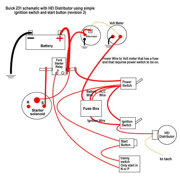
UPDATE 2: I’ve made a major adjustment to my basic wiring schematic.  This fixed my alternator issues and got my volt meter working correctly.

Major Changes:

  1. I corrected how I wired my Ford Starter Relay (aka Remote Starter Solenoid).  Basically, when the starter button is pushed, it ‘closes’ the connection in the Relay, which ignites the left side of the relay, in turn causing the starter to start the engine.
  2. While my schematic was actually correct, I had mis-wired my Delco 10si alternator because the wiring that came with my wiring harness caused me to mix up the sensing wiring and the field wire.  In my case, the sensing wiring is on the left and wired to the volt meter and the field wire plugs into the right and wired to the battery.
  3. I hadn’t added a power wire to the volt meter side.  I made sure the power wire was only powered up if the power switch was on, to reduce the chances of the batter getting drained.

final_schematic_wiring1Here’s some links I used to resolve my questions:

 
To Top

My Build: The Engine’s Running

• CATEGORIES: Biscuit This site contains affiliate links for which I may be compensated.

Below is a video that documents the third start of the engine. It’s pretty brief, but I didn’t want to do much more than idle it at that time.

The main issue with getting the engine to work was that I simply had the distributor wires  in the wrong places .. i was off by 180 degrees.  Once I fixed that, it started immediately!  Frankly, I was surprised when it started.  I only swapped the wiring because I saw someone else on the web with a HEI distributor with the wires opposite of what I had done.  Since I was out of ideas, I figured swapping wouldn’t hurt anything and, VIOLA .. it started instantly!

Once I had it started, I had to go back through and fix some of the mistakes in the wiring I had made, including discovering and fixing a key wire that ran underneath the jeep — that was a pain!

Now, most everything works.  One key issue is that the alternator isn’t working.  But, I think I should have that problem solved by tomorrow.

 
To Top

My Build: Update on Progress

• CATEGORIES: Biscuit This site contains affiliate links for which I may be compensated.

With my son Karson’s help, I got everything ready to fire-up the engine.  So, we flicked on the switches and he pushed the button … and nothing.  Such is the wonderful world of projects.

So, it was time to start testing parts to see what I did wrong.  First, we discovered the start button was bad, so that was replaced.  Then, I realized I had a loose wire, which we repaired. But, the biggest issue I had was that I wired up the Starter Relay (aka Starter Solenoid depending on the source) incorrectly.  That took a little rewiring and refiguring (see revised schematic two posts above), but we did it.  Then we tried the start button and success, the engine turned over without any unexpected noises!

Next, I realized the fuel pump wasn’t working. However, it turned out to be another wiring issue and I got that resolved.
We got to the point where gas was getting into the carb, spark was reaching the spark plugs and the engine was turning over, but it didn’t fire.

The next step was to more closely check the timing. While taking off the spark plug off the number one cylindar, the spark plug broke.  I’ve never had that happen before.  At that point it was 10pm and we couldn’t run to the store to get another plug.  That was dissapointing as I had to take the boys home the next day (yesterday).

The good news is we got really close.  It is nearly ready!   I’ve promised to get video of the engine running so they can hear it (which of course I’ll post here as well).
Best of all, though, was watching 15 year old Karson get excited about working on the jeep.  He was asking to go out and work on it, he waited patiently for things to do, and asked questions when he didn’t know what he was doing.  That experience alone is worth everything I’ve put into this crazy project.

 
To Top

My Build — Fluid time

• CATEGORIES: Biscuit This site contains affiliate links for which I may be compensated.

UPDATE:  I added all the fluids.  I installed the battery holder and battery.  The new filler tube for the tranny got installed (though it was taller than the previous one, which meant it needed some adjustments to make it fit).

I flicked on my switches and, well, not much happened.  It seems there’s a problem with my Relay, so I’ll have to puzzle through the problem.  I did a temporary bypass of the relay and discovered that some things work and some things didn’t, so I’ve got some trouble shooting to do (no suprise there).

So, work continues … 🙂

I’m dropping in fluids …. hurray!  So far, only one major leak located.  I hadn’t tightened down one of the brake lines at the master cylinder, so brake fluid leaked down to the frame, melting off the paint … That’s now fixed!

I’ve got the engine oil in the engine.  The gear oil in the front and rear differentials and the transfer case.  I got a new dipstick tube for the th-350 and will install that and put in the first four quarts of tranny fluid.  I’ll need to get the engine started and work through the gears to get the fluid to disperse so I can add more.  I’ve read the total volume will be about 12 quarts.

I’ve tightened up all the tie rod bolts and will put in powersteering fluid.  I’ll work out the air bubbles once I start the engine by turning the steering from lock to lock, slowly, with the cap loose.

Finally, I plan to try to start the engine tonight.  No doubt, there will probably be some swearing involved and my sons will learn words they haven’t heard even on South Park!  lol.

So, lots on the agenda tonight!  Therefore, I’m delaying any update until tomorrow.

 
To Top

My Rebuild — Modifying the grille

• CATEGORIES: Biscuit This site contains affiliate links for which I may be compensated.

UPDATE: I wrote this post a year ago in May.  A reader recently asked about why my headlights looked different, so I am reposting and have updated it with info from the Classic Oldsmobile Forum.

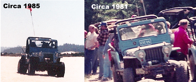
One of the modifications I wanted to make was to change the size of the headlights from 7″ to 5 1/2″ to give my jeep a little different look.  I’ve only seen these smaller headlights on two jeeps (both of which had fiberglass grilles), one set was on my first jeep, pictured to the right (which shows my first set of lights on the left and then the bigger, standard lights after I switching to a metal grille on the right), and on a jeep called Otis (still owed by the Carter’s, long time family friends who actually named me — that’s another story) pictured below (note that the positions of the headlights seems to have changed between 1981 and 1985, which I just noticed — UPDATE:  Steve Carter tells me the change was due to a rollover involving his mom during a race in 1983.  The wider lights were the result of a new, wider radiator).

otis_headlights

One hitch to my plan was that I didn’t know where to find the 5 1/2″ headlight assemblies and Jim Carter couldn’t remember where he got his headlights.

After a good deal of searching, I learned a few things about headlamps.  First, the 7″ lights were mandatory on autos sold in the US starting around 1940.  Then, in the 50s, the laws were relaxed to allow dual 5″ lights.  However, most dual assemblies were combined headlight assemblies, but I needed individual headlight assemblies.  Finally, after roaming a great local junkyard that has a ton of old cars piled two and three high I finally found the individual assemblies, which look like mini jeep headlight assemblies, on an 1959 Oldsmobile dynamic 98.

According to a helpful forum user at the Classic Oldsmobile website, the 1959 and 1960 Oldsmobile Dynamic 88 and 98s used the same size bezels and headlights (with the unique aspect that the bezels weren’t connected to other bezel parts, which makes them look like a jeep bezel), but the Dynamic 88s were Anodized aluminum, while the Dynamic 98s (like mine) were chromed.

Now that I understood what I had purchased, my first step was to creat a mockup.  Using some cardboard, I created some templates to see how the new lights might look in the grille.

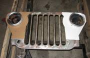
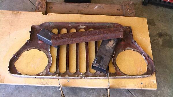
Satisfied that the look is what I’m sought, over the next couple of days I modified the grille to accomodate the smaller headlights.  The first step was to attach the grille to a flat, waxed surface.

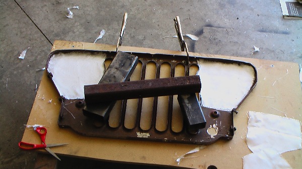
Next, I cut the fiberglass matting to fit the shape.

Continue reading

 
To Top

My Build: The front clip is together …

• CATEGORIES: Biscuit This site contains affiliate links for which I may be compensated.

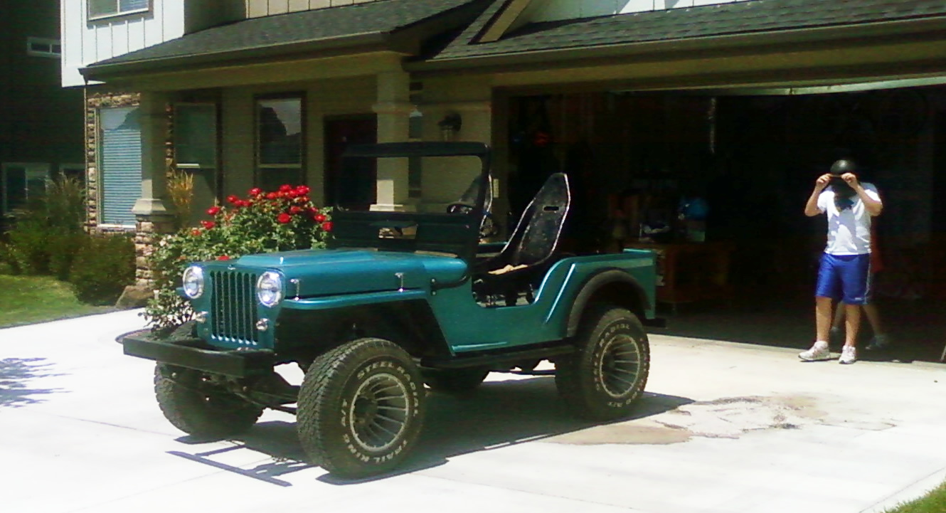
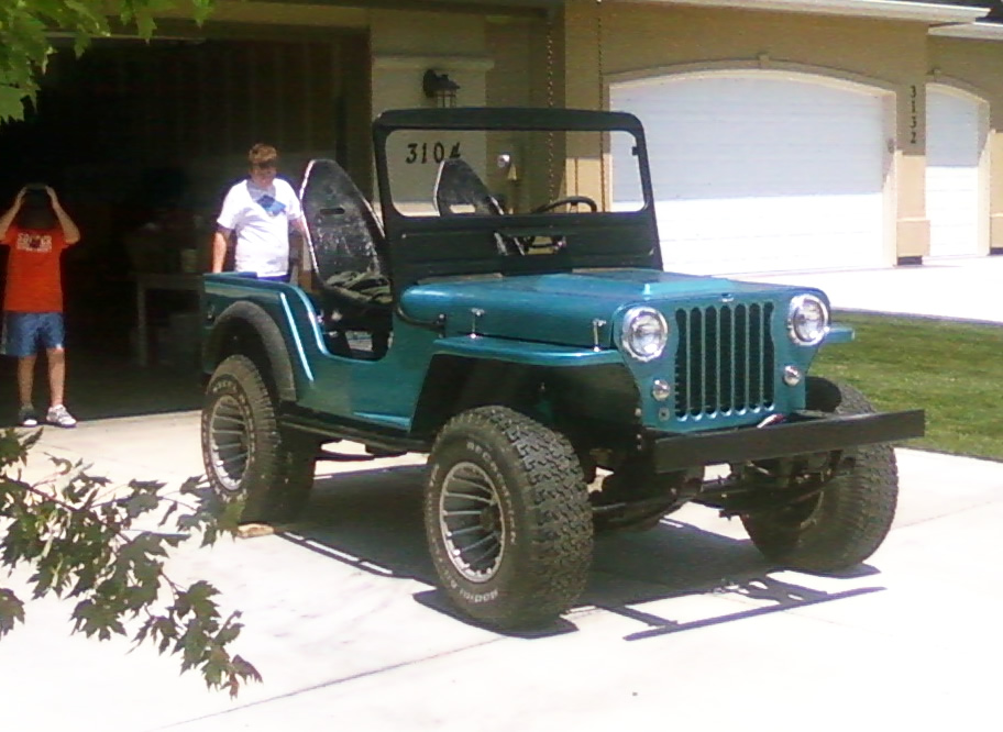
These cell phone pics and video aren’t the greatest.  I think I’ll go back to snapping pics with my real camera.  But my phone, a Samsung Instinct, is really handy for snapping quick pics and uploading them to my computer via bluetooth (much easier than an iPhone — and that’s from a Mac guy — which will only awkwardly upload photos one at a time via email).

As you can see, my sons were excited to help me.  My oldest, Karson, who turns 15 soon, has been wanting to learn how to do everything, so I’ve taught him how to use the drill press, grinder, cutter, portable drill, sander and even the arc welder.  That’s been a priceless joy for me.

I’m hoping to get it running on my return from Seattle (Monday June 29 – Friday July 5) before my kids leave in mid-July.

jeep_front_on

jeep_front_on2

jeep_front_on3

 
To Top

My Build: A Center Console

• CATEGORIES: Biscuit This site contains affiliate links for which I may be compensated.

console_finalI made more progress this weekend on the jeep.  Most importantly, I planned and excecuted a design for my center console.

My center console stands between the front seats.  It’s purpose was two-fold:  1, provide a place for me to put power and ignition/kills switches, along with a start button, and, 2, provide a more accessible location for plugging  in my cell phone (which will sit, along with a few other items, in a compact water proof bike bag that I can easily remove).

Now you ask, and reasonably so, why install a start button and switches when you have a perfectly good key switch on the steering column?

Well, that’s a good question.  There’s only one answer. I always wanted a jeep that started with a simple push button.  So, I just had to get that urge out of my system.  Trust that the key solution would have been easier, as my wiring harness was all set up for a GM column.  This meant I had to remove the GM plugs from the harness, decode the wiring, and rewire the critical wires to the correct points in the center column.

With that said, here’s my console:

After considering a variety of designs, I came up with this simple post and console design.

Below are the steps for cutting out the back of the console.  I had an old hood that I have been using for some spare sheet metal.  Below is the paper template on the hood.  Also on the hood is the bent and drilled console.

console_template_2

Next, I cut out the metal using a grinder with a cutting wheel.  Then I used a paint remover on my grinder to remove the paint.

console_template

Continue reading